
Draft Angle Guidelines for Injection Molding
Table of Contents
Draft angles are the invisible requirement on every injection molded part: a slight taper on vertical walls so the part can be ejected from the mold without sticking or scuffing. Draft is specified in degrees of taper from the vertical, and it is the most commonly forgotten detail in CAD — a designer builds a perfect box, the mold maker adds the taper, and the part comes out 0.5 mm bigger at the parting line than the drawing says. The fix is to design with draft from the start.
The standard guidance: 1° of draft per side is the minimum for most materials on most surfaces; 1.5-2° is recommended for general parts; 3°+ for textured surfaces (each 0.025 mm of texture depth needs about 1° of draft); and 0.5° is possible only on polished, shallow features with ejection assist. The exact number depends on material (PP and PE release easily; PC/ABS and nylon need more), surface finish, and depth of the feature. The full material-by-material table is in our draft angle guidelines reference.
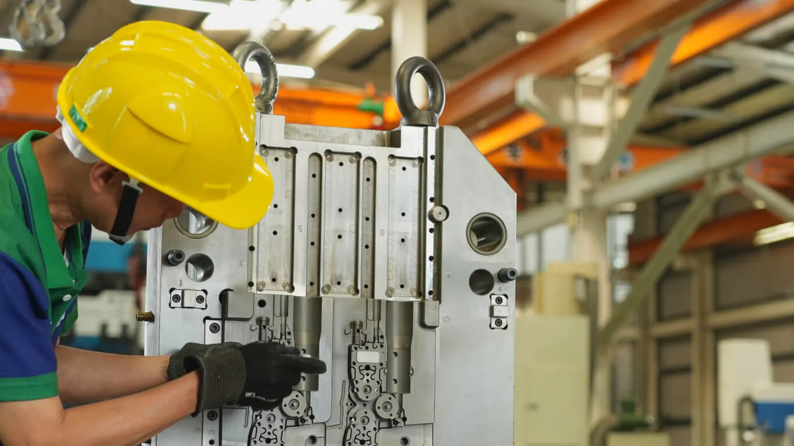
Where Draft Goes Wrong: Textures, Cores and Deep Walls
The biggest draft trap is texture. A cavity etched with a leather or orange-peel texture becomes a series of undercuts on the part surface — without enough draft, the part locks into the texture and the ejector pins gouge it. The rule: add 1° of draft for every 0.025 mm of texture depth, on top of the base draft. A D-2 texture (about 0.05 mm deep) needs 2-3° total draft per side. Cosmetic textured parts with inadequate draft are the most common first-shot failure in consumer electronics.
Cores and deep walls are the second trap. A deep rib or boss with no draft becomes a shrink-and-stick trap: the plastic shrinks onto the core, and ejection requires more force than the part can take. The standard solution is draft on the core side plus polished core steel; for very deep features, multiple ejector stages or lifters are designed in. Long, thin ribs should have 0.5-1° draft and a minimum width — ribs thinner than 0.6 mm are hard to fill and hard to eject.
Designing Draft In From the Start
The design sequence: choose the parting line first, then apply draft to every surface that runs from the parting line into the mold — inside walls get draft toward the cavity (larger at the parting line), outside walls get draft toward the parting line. A good CAD practice is to draft from the parting line in the model, not to leave it to the mold maker: the mold maker's draft changes your dimensions, and if the mating part was designed without the taper, the assembly fails. The DFM review at MOLDITQUICK checks draft on every surface before tooling — see our DFM checklist for the full review list.
When draft is genuinely impossible on a functional face (a sealing surface, a press-fit diameter), the mold can be built with the feature perpendicular and ejection handled by lifters or slides — but that adds tooling cost and cycle time, and it should be the exception, not the rule. The honest conversation: every 0.5° of draft you can add reduces ejection risk, cycle time and tool wear.
If you are not sure your design has enough draft, send us the model — we will review it against the material and texture, and flag every surface that will fight ejection. Contact us to start.
Finally, remember that draft and tolerance interact. If the drawing shows a vertical wall with a tight tolerance, the mold maker's added draft makes the dimension vary along the wall — the top of the wall measures different from the bottom. The correct practice is to dimension the part at the parting line and call out the draft explicitly on the drawing, so the mold maker applies it without guessing and the inspector measures at the right location. A drawing that says nothing about draft leaves the mold maker to decide — and the part's dimensions then belong to a decision nobody reviewed.
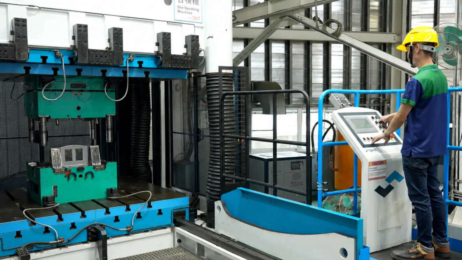
Need a quote? Contact us — upload your 3D file for a fast DFM review.
NEXT STEP
Ready to Start Your Project?
Send us your requirements — our team responds within 24 hours. Pricing and a realistic lead time come with the reply.
Written by
Ray ChanExport Brand Manager · Injection Molding, Mold Making & DFM. Ray helps global importers and integrators source factory-direct plastic parts and tooling.